Tool wear can gradually increase ignition risk in hazardous areas, even when a tool was originally designed as a non-sparking product. In this guide, we explain How Tool Wear Affects Non-Sparking Performance and provide a simple inspection and replacement process. By using X-Spark Non Sparking Safety Hand Tools, checking dimensions to 0.01 mm, recording inspection results, and replacing tools before critical wear develops, maintenance teams can improve operational safety and reduce unplanned downtime.
Non-sparking tools are manufactured from copper-based alloys, including beryllium copper or aluminum bronze, rather than conventional hardened steel. These materials are selected to reduce the probability of incendiary sparks during contact with equipment.
However, “non-sparking” does not mean “impossible to ignite an atmosphere.” A worn tool can still create danger through several mechanisms:
In flammable gas, vapor, dust, or oxygen-enriched environments, these conditions can contribute to ignition. For this reason, How Tool Wear Affects Non-Sparking Performance should be treated as a maintenance-control issue, not only a purchasing issue.
A new X-Spark tool has a controlled surface finish, accurate geometry, and a predictable contact area. After repeated use, the following changes may occur:
| Wear condition | Effect on performance | Recommended action |
|---|---|---|
| Rounded jaws or open-end edges | Less contact accuracy and more slippage | Remove from precision work |
| Mushroomed striking face | Increased deformation and impact instability | Reject immediately |
| Burrs or gouges | Localized friction and sharp contact points | Deburr only if permitted; otherwise replace |
| Enlarged socket opening | Higher torque loss and fastener damage | Measure and replace |
| Embedded steel particles | May defeat the intended non-sparking behavior | Quarantine and inspect |
| Corrosion or chemical attack | Reduced strength and surface integrity | Replace after engineering review |
| Bent handle or shaft | Uncontrolled load and possible fracture | Remove from service |
This is why How Tool Wear Affects Non-Sparking Performance must be included in toolbox talks, permit-to-work procedures, and preventive maintenance programs.
A documented inspection routine helps us identify unsafe tools before they enter a hazardous work area.
Before inspecting or using the tool, identify the site classification and operating conditions.
Check whether the work involves:
The tool selection must be consistent with the site’s risk assessment, permit-to-work system, and applicable hazardous-area requirements. EN 1127-1 and IEC 60079 series practices may be relevant to the overall explosion-risk assessment, but they do not automatically certify every hand tool as spark-free.
Cleaning is essential because dirt can hide cracks, burrs, and metallic contamination.
We recommend:
Do not use a wire brush made from carbon steel on a copper-alloy tool. Steel transfer can create a contamination problem and may affect the tool’s intended non-sparking performance.
Run a gloved finger carefully over the working surfaces. Look for:
A visual inspection should be completed before every use in a high-risk area. A more detailed inspection should be scheduled at least monthly for frequently used tools, or according to the site’s risk-based maintenance plan.
Tool wear is not always obvious. We use calibrated measuring equipment to check working dimensions.
Suitable instruments include:
Measure the tool against the manufacturer’s original drawing or acceptance tolerance. Do not rely only on general appearance.
For example, inspect:
If the measured dimension exceeds the manufacturer’s allowable tolerance, the tool should be quarantined. Precision to 0.01 mm is useful for inspection, but the acceptance limit must come from the product specification rather than an arbitrary universal value.
Copper alloys can collect iron or steel particles during service, especially around sockets, jaws, and striking faces.
Use the following procedure:
Magnetic inspection is not a complete certification method. It only supports contamination screening. If the tool has experienced severe impact, welding activity, or contact with carbon-steel components, request supplier or laboratory evaluation.
A worn tool often causes fastener slippage. Slippage increases friction, damages the fastener, and creates unpredictable mechanical loading.
Check that:
For critical maintenance, use a calibrated torque tester. Record calibration status and inspection results. A 100% inspection program is recommended for tools used in classified hazardous areas when the risk assessment identifies ignition or equipment-failure consequences.
Not every worn tool should be repaired. Removing material can change alloy composition, heat treatment, geometry, or surface condition.
Use this decision process:
X-Spark Non Sparking Safety Hand Tools should not be modified by unauthorized grinding, welding, heating, or machining.
The correct frequency depends on duty cycle and hazard severity. A practical schedule is:
| Use condition | Inspection frequency |
|---|---|
| Occasional use in a controlled area | Before each use and quarterly formal inspection |
| Daily use in an ATEX or classified area | Before each use and monthly formal inspection |
| Heavy impact or continuous maintenance | Before each use and weekly detailed inspection |
| Chemical, saltwater, or corrosive service | Before each use and after every exposure |
| Tool involved in a drop or overload | Immediate quarantine and full inspection |
| Unknown or shared tool inventory | 100% inspection before issue |
We recommend recording:
A digital asset-management system can reduce paperwork and provide a 24-hour response process for urgent replacement requests.
Early wear may appear as slight rounding or polishing. It can be difficult to distinguish normal use from unsafe deformation.
Solution: Create photo-based acceptance criteria. Compare each tool with a new reference sample and define measurable limits using calibrated gauges.
Carbon-steel wire brushes, aggressive abrasives, and unapproved chemicals can damage or contaminate copper alloys.
Solution: Provide a dedicated cleaning kit containing lint-free cloths, approved solvent, non-ferrous brushes, inspection light, and protective gloves.
Production pressure often encourages workers to keep using tools that should have been removed.
Solution: Introduce a red-tag quarantine system and maintain replacement stock. A simple minimum inventory of 10–20% above average monthly consumption can prevent unsafe tool reuse.
Non-sparking tools reduce mechanical ignition risk, but they do not eliminate all ignition sources.
Solution: Combine tool control with gas detection, bonding and grounding, ventilation, hot-work controls, intrinsically safe equipment, and permit-to-work procedures.
A tool may be marketed for hazardous environments without a clear explanation of its test method or application limits.
Solution: Request technical documentation covering:
DIN tool specifications may define dimensions or product construction, while ASTM methods may support material, hardness, corrosion, or wear evaluation. EN 1127-1 and IEC 60079 guidance should be applied to the broader explosion-risk control system. We should never treat a general standard reference as a substitute for product-specific evidence.
X-Spark Non Sparking Safety Hand Tools are intended for controlled use in environments where mechanical spark risk must be reduced. A reliable supplier should support the complete lifecycle, not only the initial purchase.
When evaluating X-Spark or any alternative supplier, ask for:
For visual reference, inspection teams can use the following product image resource:
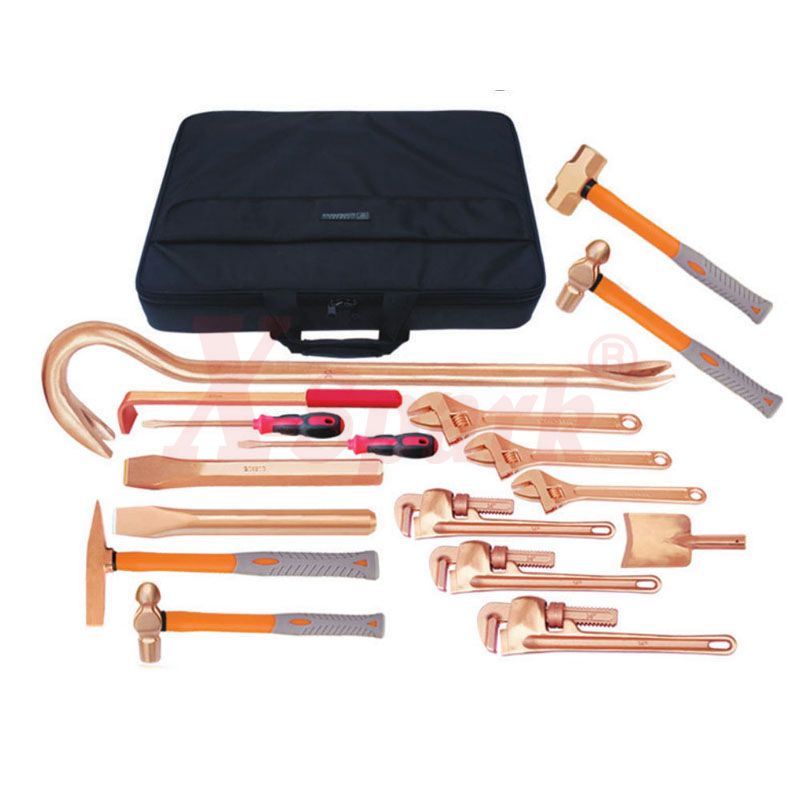
The image should be used together with technical specifications, not as the sole basis for acceptance. Product appearance cannot confirm alloy composition, internal defects, or actual wear limits.
A small, standardized inspection station can significantly improve efficiency. We recommend preparing:
A barcode or QR-code system can link each tool to its inspection history. For high-risk operations, use 100% issue-and-return verification so that every tool is checked before and after use.
Before releasing a tool for service, confirm:
This checklist makes How Tool Wear Affects Non-Sparking Performance easier to manage in daily operations because it converts a technical risk into a repeatable maintenance action.
Understanding How Tool Wear Affects Non-Sparking Performance helps us prevent avoidable ignition risks, fastener damage, and maintenance delays. X-Spark Non Sparking Safety Hand Tools should be cleaned correctly, inspected before use, measured against documented tolerances, checked for contamination, and replaced when their geometry or surface condition is no longer reliable.
Start today by identifying every non-sparking tool in your facility, assigning a unique ID, completing a 100% baseline inspection, and establishing a replacement threshold. With calibrated measurement to 0.01 mm, documented quality checks, appropriate ASTM, DIN, EN, and IEC references, and rapid supplier support—ideally within 24 hours—businesses can create a safer, more accountable tool-control program.
Previous: None
Copyright © Hebei Botou Safety Tools ( Groups) Co., Ltd. All Rights Reserved | Sitemap

 中文